Saturday, September 12, 2009

Water Rocket Launcher Construction Tutorial: Part 14

We're back again this week with another in our launcher design tutorials. We thank you for all the positive emails and encourage you to comment below so that everyone can share in your interesting suggestions! This will be a quick update, as we have been spending a lot of time on the new rockets and training a new team member since the beginning of the month. We apologize for the delay in the updates but we should be back on course now.

Where we left off in our tutorial, we had just painted our wooden launcher base. This has really improved the look and feel of the base and it really turned out well. After we buffed the paint and waxed it with regular auto polish and wax, it really popped! Take a look at the surface in the photo below! Incredible, isn't it?

We've gotten very adept at painting and smoothing out these pieces and the skills will come in handy when we have to make another batch of nosecones or fins. We will also attempt to get our rockets as smooth and shiny as that because we have some test evidence which suggests that there is a performance gain in reducing the small imperfections and seams in our rockets. We have done some testing using a synthetic wax similar to beeswax that can fill seams and voids where our rocket parts join together (such as the joint where the nose separates).
Once we had our finished launcher base buffed out, the only step left would be to put the pieces back together and call it a day. So, we began assembling the parts and mounting the hardware. The rubber feet were installed first, so that the rocket launcher base could be set down without scratching the fresh paint. Paint of this type can take several weeks to fully cure, so be careful with the finish until it has hardened completely.

The next step is to mount the launch tube on the base with the U-Bolts. Be careful not to tighten the u-bolts too much at this point because we just reminded you that the paint takes a long time to cure. You don't want to ruin the paint by tightening too much just yet. Just snug up the nuts and you will have a functional launcher. You can return later and torque them more after the paint cures, if you wish.
The last step of our assembly would be to replace the cable-tie hardware, but we have a problem. It's not a show stopper, and we could have finished the build here by putting the rest of the parts together, but the PVC launcher looks a bit shabby in comparison.

But don't worry, we have a way to really make that hardware sparkle, and we will bring that to you in our next launcher update!

See you all next time!

Saturday, August 22, 2009

Project 3000 Update: 08-22-2009

It has been another amazingly productive week here at U.S. Water Rockets. We've made a major advance in our nozzle design which has been tested on the bench and proved to be the solution to a major impediment to our world record flights. The issue is an effect we have dubbed "Blowback".

The way we discovered this issue is thanks in part to a question posited by our new friend Steve Porter, who frequents the WRA2 Water Rocket Forum, and noticed something odd in our HD Video from Video Log #1.

Steve noticed that when the rocket was coming down from apogee, the view in the camera lens became blurred and distorted. We had noticed this ourselves back at the time of the launch and we had attributed the effect to fogging of the camera lens. We believed that the heat from the camera and the cold air had somehow condensed moisture and fogged the lens. Since the rocket took a long time to retrieve from the tree it landed in, there was no fog on the lens when we recovered it, so we had no proof. You can see how blurred the HD video image became near the end of the descent in the image below.
We were discussing the theory with Steve and he suggested an alternative idea that never occurred to us. His suggestion was that water dripping from the nozzle would have been blown along the outer skin of the rocket as it fell rapidly thanks to the partially failed parachute. The water drips eventually were blown back up to the nose of the rocket where they collected on the rear-view mirror we placed there. The drops of water eventually collected there and blurred the lens.

We consulted some of our more recent videos and noticed that there indeed was a good deal of water streaming from the nozzle after apogee. The water would drip off and fly down below the rocket. The water could easily be seen spraying around the downward looking views in the HD video. Fortunately, we had a recent launch which had a partially tangled parachute resulting in another rapid descent and just before splashdown we did notice a slight amount of fogging in the video. We believe that this confirms Steve's brilliant observation regarding the water.

We went back and looked at some of our other recent flights and we realized that there was a lot of water dripping from the nozzle during the descent phase. Notice how many water droplets are visible in this recent still-frame shown below.
That was not the end of our story, however... we discussed the dripping water and as you would expect we concluded that it would not be a problem for video in normal flights. We did decide that the amount of leftover water inside the rocket was excessive. It amounts to useless dead weight that needs to be carried to apogee, and it also equates to a loss of thrust that could have been used to lift the rocket.

We ran some static tests and realized that the blowback effect is caused when the water level becomes shallow enough for the air pressure to "punch" through the water, forming an air column through the water and actually splashing the water upwards above the air pulse and all over the inside of the rocket, where it would slowly run down and out long after the rocket had reached apogee.

We have made some changes to our nozzle inlet and added an inverted cone shaped baffle to the rocket just above the nozzle, and we have reduced the amount of blowback by 2/3 what it was. We were able to test this in the lab by weighing the rocket before test firing and then weighing it after test firing and subtracting the mass of the dry rocket to determine the weight of the water remaining. Subsequent test flights have much less water droplets visible, so we are confident we have solved the problem. See the improvement in the image below?
We will be using the new nozzle design in our next round of test launches. A report on the new nozzle performance will be forthcoming. Once again a big thanks to Steve for his insightful observations!

See you next time!

Saturday, August 15, 2009

Water Rocket Launcher Construction Tutorial: Part 13

It has been another long and productive week here at U.S. Water Rockets. We have been working very hard trying to solve a few problems with our Project 3000 design and have made some excellent progress. We will not know for sure if our situation has been corrected completely until our next launch day, which may be this weekend if the weather forecast holds true.

You can expect full details of our progress in an upcoming installment of our video log series, as we have taken a great deal of imagery and video footage of the progress as we move along.

Meanwhile, we are continuing to refine our launcher tutorial and this week we will be picking up where we left off in our last part of this series where we had just completely painted the wooden parts of the launcher with a product called "Aero Gloss", which is a wood sealer made for modeling applications. This stuff is awesome because it seals wooden pieces and prevents the grain from absorbing paint. The end result is a perfectly smooth finish.
 Even if you are not building a launcher like this one, you will be able to make great use of this product because it can be used on any wooden part of your rocket and will allow you to make it perfectly smooth and really look great with the methods we explain here. For example, we use this product also on our wooden nosecones and rocket fins, for really nice and perfect looking pieces.
When we left off, we had painted the first coat of Aero Gloss on the launcher base, and we allowed it time to completely dry. According to the instructions, you should now sand the wood with fine grit sandpaper and smooth out the wood before the next step. We took progressive gains of sandpaper from 220 to 600 grit and sanded the base. When we were done we use  a towel to wipe off the dust and then compressed air to blow off any remaining particles. We don't want dust to get trapped in our finish, so removing it is a good idea.
A second coat of Aero Gloss was applied to the base at this point. Things went pretty much the same way as they did with the first coat. We found that a good idea is to hang the pieces with a screw temporarily inserted into the hole made for the rubber foot is a nice way to suspend the part so that it can be painted with aero gloss in one coat all over instead of painting one side at a time. The screw in the foot hole can be used to hang the part from a string so that it does not touch anything and ruin the paint.
We actually took the precaution of doing a third coat of Aero Gloss sealer with rounds of sanding and cleaning in between the coats and following the last one, just to be on the safe side. Since this launcher is featured as the sample on our website, we figured we had better be 100% positive that the launcher was as defect free as humanly possible, so we went ahead and did the extra steps. It only added an extra day on the build because we allowed for the final coat of Aero Gloss to dry between the coats and the extra sanding certainly can only make things smoother. While drying out the launcher base, we were able to go to Wal*Mart and pick out a nice bright yellow color for the base color. We thought that the color would look good when combined with the other colors we have planned and would be bright enough to act as a safety precaution as well. We even got "FREE 33% More" paint!
We hung the base up by the screw once more and began applying coats of the yellow paint. Avoid the temptation to douse the whole object with paint because the technique of using many thin coats will produce a much nicer result. It will take longer, but it insures that the paint never becomes too thick to cure properly in the time allotted in the instructions. It also helps produce an even coat without any runs or drips.

We had a small problem in that a little flying insect decided to land on the fresh paint and walk around before being overcome by the fumes but not before leaving footprints as well as his feet, legs, and body stuck in the paint. Having done several thin coats at that time we were able to sand off his handiwork (or footiwork) without cutting through the paint and add another coat on top. The damage is completely fixed now. So remember the benefits of many light coats!
One final thing we discovered was that spray painting the hanging base was not as easy as brush painting it. The spray causes the base to begin to spin around due to the pressure of the paint hitting it. We came up with another idea, going back to painting the bottom side first and then inserting four screws into the leg holes and flipping the base over and standing it on the screws so no paint touched anything, then painting the top side. This worked very well, and we found that painting the base while sitting horizontal was easier to do and that gravity assistance helped get the paint layers on easier. We will remember this in the future.

We are letting the paint cure fully for a few days so we will be back collecting data for Project 3000 in the nice weather. This will give us some more multimedia for our future videos and make sure this paint is not going to be tacky when we go to finish the base build next week.

Thanks again for joining us. See you next time!

Saturday, August 8, 2009

Project 3000 Video Log #1

We've been very busy the past few weeks with more tutorials, but we decided to take a little time during a rainy period to put together the first episode of our Project 3000 Video Log Series. This series began at the end of the Summer of 2008 when we first started working on the new designs for the new rocket.

The design was built around the idea of lifting a fairly hefty payload inexpensively to high altitudes while recording video and logging payload data. The requirements for the payload required us to use a larger tube for the payload section, so we decided to use ordinary soda bottles for the new rocket. A side benefit of using ordinary soda bottles was that it would eliminate criticisms that our FTC rockets had advantages over "pop bottle" rockets.

Prior to the inception of the project, we had been experimenting around with a new camera design based on the controller which will be showing up in the next generation of a famous mobile device. This design is much more advanced than our last one and has programmable resolution and bit rate. The appeal of the new design is that we can take video in any resolution including Full 1080p HD video.

The first Video Log describes the origin of Project 3000, and shows off our very first test flight. This flight was launched in December of 2008 on the day after Christmas. We gained a lot of experience with cold weather launching and the new HD onboard video showed us some issues with the design that we want to investigate.

We took the footage filmed that day and over the past few months and we put together the Video Log series. We hope you enjoy these videos and will subscribe to our channel and of course leave comments!

Enjoy the video!!!!


Tuesday, August 4, 2009

Video Log #1 Coming Soon!

Hello again! This is just a quick post to let you all know that we are hard at work producing our first Vlog post for a new project. We will be posting the first installment of the Project 3000 Video Log in a few days!

See you then!

Saturday, July 25, 2009

Water Rocket Bottle Coupler Construction Tutorial

This week we will be presenting an article detailing how to build connectors to join together multiple bottles by the threaded necks. This type of bottle connector is generally used when making large volume or extended length water rockets like some of the rockets you may have seen on the TDFwaterrockets blog.

The connectors we will be building today are an advantage in this type of rocket because they allow for a modular approach to be applied to your rocket design, which simplifies construction and repair of a damaged rocket. There are commercial products that one can purchase called "tornado tubes" which some water rockets are constructed from, but these are not designed for significant pressure and cost more when compared to building them yourself. Doing things yourself is a lot more satisfying, and is a great lesson for children in managing money by doing for themselves rather than buying something overpriced off the shelf.
Getting back to the advantages of a modular rocket, construction effort is reduced because a module rocket can be built to sections screwed together with these connectors as opposed to one contiguous rocket made from multiple spliced bottle sections which all have to be perfect. In a module design, each module can be built and tested individually and if one happens to be defective you have not wasted the entire rocket because you simply replace the faulty module. This holds true if the rocket ever becomes stressed or damaged as well, where bad modules are replaced instead of scrapping the entire rocket for one leak.

The downside of a module rocket is that the modular sections and the connections between them add extra weight and are less aerodynamic than a standard spliced rocket, so they are great for experiments, but not really appropriate for setting any type of record. But for the casual water rocket enthusiast, these make life so much easier that we are devoting this update to showing how to build your own bottle couplers.

Let's begin the tutorial, shall we?

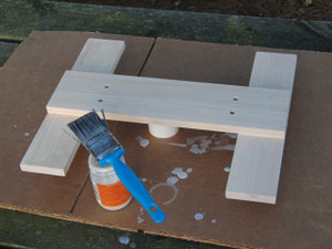
The first thing you will need is a tube of the "Low Surface Energy" glue we featured in our June 6, 2009 Update. If you want to learn more about this amazing new glue we discovered, please go back and check the update. We are finding quite a few uses for this glue and we think you will too!
You will also need to collect up some extra bottle caps. They come in all sorts of colors, so be creative and pick colors you think will look good on your rocket. Be sure to find caps that come from carbonated soft drinks and not those from water or juice bottles. The carbonated bottle caps have a built-in seal made of a soft rubbery material that will allow the construction of this coupler design without needing o-rings, which is a cost savings for you!
The  last ingredient in our recipe is a short piece of T-8 Fluorescent Tube Cover (FTC). Be sure and get T-8 tubes and not T-12 tubes, because the narrower T-8 tube fits snugly over the bottle caps. it almost looks as if whoever designed the T-8 tube had water rockets in mind when they picked the diameter! This is a lucky coincidence!
These parts, with a little effort and some simple hand tools are all you need to create these modular rocket couplers.

The first step in construction is quite simple. We need to use some sandpaper to roughen up the surface of our bottle caps to increase the bonding strength of the glue joints. Be sure to roughen up the entire outside surface of your bottle caps, including the sides. You will also want to scuff up the inside of your T-8 FTC a bit as we will be gluing the inside of the FTC as well.
Here are some of our sanded and un-sanded bottle caps side by side, so you can see how nice and rough they are. Before you go any further you should wash the caps in a strong detergent to make sure any soda and oils from your fingers are removed. You can also wipe them down with alcohol after you wash them to remove any other residue that the detergent couldn't remove such are sticky glues from labels or price stickers.
The glue we are using is specifically designed to work on Polypropylene and Polyethylene plastic, which is the type of plastic which the bottle caps are made from. If you refer back to our initial report on this glue, you will see how to identify these kinds of plastics. The glue we discovered is a two part glue which consists of a primer activator and a CA glue that is applied after the primer has evaporated. We used the Loctite brand glue for our tutorial here because the primer comes in a felt-tip pen applicator, which can be closed and reused multiple times.

The super-glue brand adhesive come with 2 vials of primer activator and these cannot be closed once opened, plus the adhesive part comes in a gel form which is great for some applications but we did not think it would flow as well as the less viscous loctite brand, so we did not use the gel.
The next step is to cut a piece of T-8 FTC that is twice as long as a cap is tall. A simple way to do this is to stuff a pair of caps inside the tube together and trim off the overhanging ends of the FTC tube and then push the caps out of the resulting cylinder of tube.
After the primer has fully evaporated, we apply the CA adhesive to one of our caps, coating the sides and top of the cap with a thin layer of adhesive. We then slide the cut section of FTC over the cap and push the cap all the way flush with the end of the FTC. Make sure the threaded side of the cap is facing outwards before the glue starts to set because you will have a few seconds to correct the mistake and that's not very long. The other cap is quickly coated with glue and slid in the opposite end of the FTC with the threads facing the opposite direction. Quickly clamp or press the caps tightly together and leave the glue to cure to full strength.
Here we have pushed one cap in the FTC already and the other one is ready to go in. We discovered that screwing a cap onto a scrap bottle before applying the glue to the outside allows the bottle to act as a "handle" so you can pick up the caps and push them in without touching the glue or getting it on your fingers or tools. Feel free to use this method as it will save you a ot of headaches.
Once the glue is cured, you will take a drill or a hole saw and cut a hole through the center of the bottle caps to allow air to pass through the connector. We used a hole saw for our holes because the center drill in the saw was very easy to center on the end of the bottle caps and get a perfectly centered hole through the middle without wandering off center. Since we use the built-in seal on the bottle caps in place of an o-ring, we wanted to be sure our holes were centered.
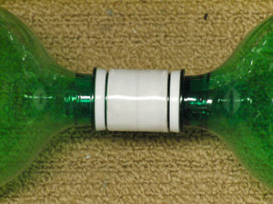
We noticed that the cured glue turns a whitish color which doesn't look spectacular cosmetically, except on the couplers we made using white bottle caps, which turned out fantastic looking. It's not a big deal and in any case the FTC can be painted to any color you want if you wish.
Notice how nicely the plain white couplers turned out.
The final weight of our couplers were measured at 6.2 grams, which is really quite good.
We waited 48 hours for the plastic glue to fully cure and then decided to give the couplers a good pressure test, just to make sure that they would hold up. We built a little test rig to pressurize a pair of bottles coupled with one of our custom built bottle couplers. The rig consisted of a spliced bottle with two female ends and a cap with a schraeder valve on one end. The opposite end connected to a second bottle with one of our couplers and the whole system was filled with water as a safety precaution before pressure testing.

By filling the setup with water, there is little air space inside the test rig and if something fails there will be less energy contained inside to cause harm in the event of a failure. Only compressed air inside the rig can store energy, so the incompressible water will take up room and reduce the available kinetic energy storage space, making the test much safer.

We pressurized the rig to 130PSI and left it there for 30 minutes. No water leaked out of the coupler and the pressure remained at 130 the entire time, so we concluded that the couplers passed the test with flying colors.
We decided to test a coupler to find it's failure point so we ramped up the pressure to find the point at which the coupler breaks but the test rig exploded at 145PSI before the coupler failed. We concluded that the couplers would be much stronger than any bottles we could splice, so we were pleased with these results.
That is all the time we have this week. Thanks for joining us, and we will be back next week with another update. We have quite a few new developments to report on so check with us next time for more surprises!

See you next week!


Saturday, July 18, 2009

Water Rocket Launcher Construction Tutorial Part 12

This week we have been very busy going over our experimental data which we were fortunate enough to obtain during the recent period of favorable launch winds. As a result of the data analysis we have concluded that we need to redesign the tail section of the rocket we are constructing for Project 3000. This is a minor setback, but the results should be worth the extra effort. We are planning a series detailing the experiments and the results which we will share with you in the coming weeks. First, we have to get back to our nearly finished tutorial on the launcher construction we had left hanging a few weeks ago.

This week we are starting to show some of the ideas we have come up with that you can apply to your launcher or your rockets to make them stand out from the crowd. These ideas are really just the finishing touches that we came up with when we were inspired by the finely crafted water rocket and launcher designs we have seen posted on the Water Rocket Forum by some of the members such as Batkiter and Skuula.

To begin with, we want to present you with a really interesting little detail that has not been given any attention and that is the cable ties. We have discovered that there are some really funky looking brightly colored cable ties on the market now, and they can really dress up your launcher if you would like to add them in place of the standard ties.
This particular package contains a rainbow assortment of day-glo colored cable ties and those would be a fun addition to any water rocket launcher you are making. The kids really go for the brightly colored launchers and so if you are looking to make something that will be appealing to children then these ties would be a great addition to your design.

Note: this particular style of cable ties is not listed as suitable for outdoor use so bear in mind that they are not UV resistant. If your launcher is made from PVC pipe then you already are aware that the pipe itself is not UV resistant, so you should not be storing it outside where it can be exposed to the sunlight for prolonged periods of time. UV light will eventually cause the PVC pipe and the cable ties to become brittle. A failure of the cable ties would likely result in a harmless self-launch of the rocket but a failure of the pipe could produce an injury. Always be careful with your launcher and check it frequently for signs of wear or damage to prevent accidents.

Most of you are never going to store your launcher outside in any case, because you are going to be so proud of the way it turns out you will proudly display it in your trophy cabinet inside your house (just kidding!)
If you are building your launcher out of CPVC or metal parts, then it can be stored in direct sunlight because these materials are designed for outdoor use. In that case, you will want to find cable ties which are rated for exterior use, such as the ones we originally made our launcher from. Typically, you will find that the ties which are black in color have UV protection, so if you are having trouble locating UV protected ties, look for black ones which should narrow your search.

Our next idea we would like to present is finishing the base of your launcher off with some nice paint. Of course we don't mean to just go out and slap a coat of house paint on like you would a patio chair or deck. We suggest you treat the launcher as you would a finely crafted model, and give it the appropriate attention to detail that will make it really professional looking.
By now we have told you to sand the base smooth enough times that you have a really nice smooth finish on the wood. If you do not, you will need ti sand it right now before you go on! The reason we want the base sanded is because we are about to apply a wonderful product we have been using on our nosecones called "Aero Gloss". This is a sealer for wood which will give it a really nice smooth hard finish and help prevent the grain of the wood from showing. We highly recommend using this product on wooden parts of your rocket, especially balsa wood parts. It will prevent them from absorbing moisture and gaining weight in the process. If the air is humid you will want to dry your parts in an oven before sealing them, just to insure they are as light as possible. For parts that do not fly on the rocket you don't have to worry about dryness.
What you will be doing now is painting a nice coat of the sealer on the wood. Pay close attention to the ends where the end grain of the wood is exposed, as this is the most absorbent part of the wood  and needs extra sealer to fill it in.

You should allow the sealer time to dry according to the directions and once it has dried completely you will sand the surfaces with very find sandpaper and reapply the sealer again for a second coat. If you have some tack cloth you can wipe down the surface after sanding to make sure no dust or fibers are left before you apply the sealer for each coat.

We plan on applying several coats of sealer to our launcher base, which is going to take several days time to cure and sand. We will have to leave with this much progress for the week and hopefully we will have time to complete the base for next week's update.

Thanks for stopping by. We will see you next time!

Saturday, July 11, 2009

Progress made and more freaky weather delays

Hello again everyone! We have been having some very bizarre weather this year and we've got another freak storm to tell you all about. There has been an unusually high amount of thunderstorm activity in our area for the past couple of weeks and this culminated in a very strange storm the likes of which we have never seen in our area than anyone on our team could recall.

The crazy weather has kept us really busy and we were unable to get online last week with our usual update. We are getting caught up and things should be back to normal quickly.
It all began last week we were minding our own business building and testing our rockets and we were actually trying to take advantage of the weather pattern because the conditions that cause thunderstorms tend to produce very favorable launch conditions in the hours before storms form. This can lead to spectacular cloudy vistas and scenic panoramas from the rocket. The conditions were perfect for test launches and we had conducted several experiments in the days before the freak storm hit.

We are happy to report that we have narrowed down the problems we have been having with rocket spin to an issue with our fins. We have not exactly confirmed the cause of the problem but we were able to change the design of our fins and correct the spinning to a very acceptable level.

Our success was interrupted by a freak series of storms that rolled on through over the course of several days and caused a lot of problems for local property owners and members of our team. The conditions must have been very unusual in the upper atmosphere, causing marble sized hailstones to form high in the sky. Hail of this size is very rare in this area, where we typically see hail the size of a pea if we see any at all. You can see the size of the hail as compared to a U.S. Quarter coin in the image below. However, the size of the hail was not the only strange thing...
In addition to the unusual size of these hailstones is the amount of them! Look at the image below to see just hod dense the accumulation of hail had gotten. This amount of hail is really unusual and it caused a lot of damage to the trees in the area which were sprouting new growth for the year. The pummeling of hailstones really devastated a good portion of the new growth and brought down a lot of the leaves and needles on the trees. A lot of small branches came down along with the leaves, so there was a lot of cleanup work to be done.
Along with the hail storms also came severe lightning as well. The home belonging to one of our team members was struck by lightning and the discharge destroyed some of the lighting fixtures and appliances. With all the cleanup work and repair work going on so that we could celebrate our annual the 4th of July Holiday party, we got a little behind schedule on our update.
Now that things are all cleaned up, we have resumed our testing activities. This past week we were able to test a new idea to provide a new camera "view" from the rocket that nobody has ever obtained before. Unfortunately, the new idea malfunctioned on the first test and needs a few tweaks before we are ready to go live with it. With the weather pattern the way it has been, we have been very lucky to have made a lot of test launches for fun new ideas like that.

We are currently also working on an idea to help stabilize the rocket when it descends on the parachute as well as when it goes up. This should help make our videos sharper and remove the blurring induced by the spinning and swinging motion of the rocket on the parachute.  We will be bringing an update in the future showing our progress with these experiments. We are taking advantage of the weather and have not had much time to document the breakthroughs.
That's all for now. The unusually good launch weather is forecast to continue for a while yet, so we are getting in several launches each launch day and this has really advanced our progress well ahead of where we planned to be at this time. It has afforded us the chance to run some additional experiments and we have learned some great things about our current fin design. When the winds pick back up we should have the time to compose a complete report.

We're glad to be back! See you next week!

Wednesday, July 1, 2009

Some cool Water Rocket Videos


This is a video we shot a while back that went 2,068 feet in altitude (630M) as part of our last published world record flights.

Saturday, June 27, 2009

Water Rocket Construction Update: 06-27-2009

Hello again everyone!

It's been a long week of construction and testing here at U.S. Water Rockets. We have been working for some time to meet some deadlines on our Project 3000 design. However, we have made an amazing discovery that we would like to share with everyone out there. We are proud to be the first team to share publicly an amazing find we made while doing some research for X-17.

What we have discovered is not one but TWO commercially available adhesives which are designed to bond with low surface energy (LSE) plastics. "Surface Energy" is defined as the ability of an adhesive to "wet out" the surface of the plastic to allow adhesion. Wetting out refers to how well a liquid will flow and ultimately cover a surface because this increases the area of contact. In general terms, maximum adhesion develops when an adhesive thoroughly wets out the surface to be bonded because the greater the overage the more area for the attractive forces to hold the bond.

Surfaces with high surface energy (HSE) generally wet out readily with conventional adhesives and form strong bonds easily. LSE plastics do not wet out well and this can be observed by liquids "beading up" on them. They often posses a waxy feel and appearance.  A quick test for a LSE plastic is to pit water on it and see if the water beads up on the surface. If it does the plastic is usually LSE and hard to bond.

LSE plastics include Polyethylene and polypropylene, which are common in plastic containers and packing materials. Of particular interest to water rocket builders is the fact that most soft drink containers use a cap made from Polyethylene. Traditionally, these caps cannot be used easily because of the inability of existing adhesives to bond with them. The ability to bond to caps is considered one of the "Holy Grail"s of water rocketry.

We have recently discovered what promises to be a solution to this problem, making various types of nozzles and interconnects possible to create for the average builder with no special tools!
 First up is Super Glue Brand "Future Glue Plastic-Fuse", which is a fairly standard Cyanoacrylate glue that is supplied in a blister package with two small glass vials of a chemical primer that must be broken open and used immediately on the LSE plastic surfaces. After application of the primer chemicals the remaining primer evaporates and cannot be saved.

Once the primer is used, the provided CA glue can then be applied and the joint glued normally.
The drawback of this product  is that you only really get two chances to use the glue, even though they provide a generous amount of primer you can only use it one time. The only solution to this is to prepare all your items and glue many of them all in one session.
Our second product is the Loctite Corporation's "Plastic Bonder". This is also a two part glue with a standard CA adhesive and a preparation chemical they call an "activator". The difference is that this product supplies the "activator" chemical in a small pen like applicator which has a tip like a felt-tipped pen and a cap that can be replaced to retain the activator when not in use. The number of times this version of the adhesive can be used is much greater than the adhesive from Super Glue.

We are currently in the process of constructing some bottle couplers (often called "Tornado Tubes" using these glues and we will be performing a complete battery of tests to determine the best glue of the two.

Stay tuned for our full report coming up soon!

Saturday, June 13, 2009

Project 3000 Flight Testing and Water Rocket Launcher Construction Tutorial: Part 12

 Hello again everybody. This week we are going to have a brief update in our tutorial on building our Water Rocket launcher. The update will be somewhat truncated, as we have had a launch window this afternoon and we were able to perform some additional flight tests on Project 3000 that we were not expecting to get done so soon. The forecast for the day was for rain and wind blowing in the wrong direction, but there was a brief period of time where the sun was out and the wind had not shifted and we decided it was suitable weather for a test launch.
As you can see from the above photograph extracted from the on-board camera we flew today. the test flights went very well. Overall, we are very pleased with the progress of Project: 3000, and we were happy to have been able to get the rocket launched with only a small time window available for launching.

We must credit the teamwork and the skill of the entire U.S. Water Rockets Team for getting these launches done so rapidly. The procedures for prepping each launch have been optimized and refined by each team member over the years as we have continued to compete in the WRA2 World Record Competitions which stipulate that a record consists of an average of two flights within a 2 hour time period. The practice and skills the whole team has gained in this competition has paid off today with a total of three test launches in under 1 hour and 53 minutes! Great work, guys!

Now that we've bored you again with our launch discussion we will get back to the launcher tutorial we have been bringing you. This week we are going to start to show you how you can add some great finishing touches to your launcher to really make it stand out in the crowd of water rocket launchers. You have worked hard on your launcher up to this point and now it is time to really make the hard work pay off.
To start off the launcher upgrades we will be adding some nice rubber foot pads to the launcher, so the launcher can be used on any surface without slipping or sliding around. The rubber feet will also work well when you store your launcher because they will not scratch anything you set the launcher on in your home when not in use. For our rubber feet, we picked some that came with screws to hold them in place. You may wish to simply get some self adhesive feet for your launcher, but we liked the shape and size of these feet so we went with them.
The one issue with these particular feet is that they came packed with screws that were far too long for the legs of our launcher and had we used the included screws then they would have protruded right through the legs. Instead we bought a small bag of self-tapping screws that were the proper length for our legs.
The first thing we want to do is mark out the locations for the rubber feet. We chose to center them on the ends of the legs in a nice symmetrical way. Here is a neat trick to locate the center of your boards. The first thing to do is mark a line the same distance from the end of the board as the width of the board. This will create a perfect square shape with the width of your board as the length of each side. You will do this for all four legs on the bottom. If you happen to have a leftover piece of the wood you used for the leg, you don't even have to measure with your ruler because you can just use the piece of scrap wood to mark off the width.
Once you have marked off the square you will take your ruler or a straight edge of a board and draw the diagonals for each corner of the square you just scribed onto the board. The result will be that the diagonals will intersect at the exact center of the square and produce a perfectly centered location for the rubber foot. Do the same thing on each leg of the launcher and locate the remaining feet.
The next step is really simple. All we need to do is use a small drill bit to frill out some pilot holes to locate the feet at each intersection of the diagonals. We chose to drill a pilot hole on each leg because the rubber foot covers the lines we just drew and so even though it is possible to put in a self tapping screw without a pilot hole we decided that it would be best to use them so we can be positive that the screws were in the exact spot we wanted even though we could not see the marks under the feet.
Now we can put the screws in. We made sure to use stainless steel for all of our metal components because it really resists rusting. We highly recommend it even though the cost is slightly higher.
After you add all 4 feet, the launcher should look like the bottom view photo shown above. Pretty nice looking, don't you agree?
Above you will see the completed feet in use. The launcher looks that much cooler now and will not scratch the table. Another benefit is that if you use the launcher on a hard or abrasive surface the feet will actually protect the launcher from coming into contact with the surface and getting all scratched up.
 
That's it for now. We are planning on spending the evening analyzing the test data we acquired from the launches we did today. We hope you will come visit us again next week when we will bring you our next update.
 
Thanks for visiting!

Saturday, June 6, 2009

Water Rocket Launcher Construction Tutorial: Part 11

Welcome back! We hope that everyone has had an enjoyable and productive week and you are ready to roll up your sleeves and get back to work on the launcher construction. In this chapter of our epic saga, we are going to be adding a remote release mechanism to our launcher.

A remote release mechanism is necessary because we are working with pressurized air inside a plastic container which could burst and cause injury (possibly severe). You will need to be able to operate your launcher to fire the rocket from a safe distance. Whether you plan on holding your own friendly competition or choose to compete internationally with water rockets around the globe in the WRA2 record competitions, you will need to abide by a water rocket safety code which will specify the minimum safe distance you need to be from the rocket.

For our design, we are using a very simple and easy to fabricate release mechanism. The parts we need to obtain are some screw eyes and some strong string. We chose this fluorescent yellow string because of it's obvious high visibility. This is a safety feature to help prevent someone from accidentally tripping over the string and launching their rocket by mistake.
For our release to work easily, we want to be sure that the launching collar holding the cable ties against the nozzle of the rocket is pulled perfectly straight and parallel to the launch tube and cable ties. To make sure the collar is pulled perfectly straight and evenly we need to be sure the screw eyes we will be using to guide the release string are aligned well and are symmetrical on either side of the launcher.

To help align our screw eyes, we are using our square to draw a line along the center line of the launch tube. Fortunately for us, there is a mold line exactly bisecting the 90 degree elbow at the base of our launcher, so we just lined our square up with the mold line and drew our line at the center of the launch tube onto the base board. If you don't have a mold line you can use your eye to estimate where the line should be or measure to find the location of the center of the launch tube and draw your line there.
Now we mark some eye locations along the line we just drew. We wanted to make sure that the eyes were spaced farther apart than the width of the U-bolts so that the release string would not rub on them so we picked a measurement that was outside the U-bolt width and just made sure to use the same measurement from the edge on either side of the launcher.
Once we had our screw eye locations, we used a small drill to make some pilot holes in the wood to insure the screw eyes were in the right spot and could not go in crooked from hitting the grain of the wood. It's always a good idea to make a pilot hole when screwing material together like this.
Below you can see what the finished eyes look like. Be sure and twist them so they end up perpendicular to the launch tube as shown in the picture below. If you have them parallel to the launch tube the string will not feed through them from the proper direction and the mechanism will be difficult to operate due to friction.
The next steps we need to take are to measure out about three feet of the release string and fasten it to one side of the release collar. The other end of the string will feed through the eyelet on the side of the launcher which will face away from the operator and come out of the side facing him/her. If you put it through the wrong side you will realize the mistake in a few minutes and then you will have to take the string back off and start over.
The release string will now cross over to the screw eye on the opposite side of the launcher and you can feed it back into the other eyelet from the side facing the operator to the back side and up to the hole in the opposite side of the release collar. Tie the release string onto the collar at this spot.
The remaining roll of release string will tie onto the piece we just connected ot the launcher forming a "Y" shaped pull string. You will want to tie the main roll of string in a knot that can slide freely from side to side in such a way that it will center itself when pulled tight and will pull evenly on each side of the launcher.
If you're building this for a scout troop you can use this opportunity to demonstrate some of the more practical knots and use the example to illustrate how some specialized knots have practical uses in real world situations!
Everyone else can just make a loop around the release string with the rolled string and tie it back to itself!
When you are finished, you can now give the launcher a quick test. Push the collar up onto the nozzle of the bottle and see that a yank on the release string will pull if off the nozzle without any trouble.
If you sense a lot of resistance you can apply some cooking oil spray to the cable ties and this will lubricate them so they slide freely. You may wish to apply some lubricant now regardless because you may want to launch some high pressure rockets and the lubricant will help release them with higher pressure inside, as the pressure can increase the friction of the collar.
At this point you can take your launcher and start flying! Congratulations!!!
However, we have some suggestions coming up next week for how to improve the launcher and finish it off professionally. You may want to come back and see our ideas before you start launching.
We were able to spend most of the day today working on the launcher enhancements because the materials we ordered for Project 3000 did not arrive in time for construction as planned. We should have what we need within a day or two. We look forward to bringing you another updated on Project 3000 shortly. In the meantime we will put the finishing touches on the launcher enhancements.

Thanks for visiting, we will see you next week!